For this I chose the Tsunami TSU-750 Light Logging decoder with a 3/4" speaker and enclosure. It will be a tight fit.


I had decided to remove the Bachmann board and "hard wire" the decoder in place, mainly because the operation was erratic, the unit ran well forward, but terrible in reverse. The loco ran excellent before this upgrade with a standard Digitrax Decoder, so I suspected electrical/electronic issues. When I hardwired the decoder, I had no movement forward or reverse, but the sounds worked perfectly. After some troubleshooting with a multi meter, the decoder was not putting out any voltage to the motor. I went to the Soundtraxx website, downloaded the warranty/repair form, filled it in and mailed it. A new decoder arrived in the mail Wednesday, no charges to my credit card and completely covered under warranty. Thank you Soundtraxx. The pictures below show how I hardwired the loco, using heat shrink tubing (recommended) although I don't recommend using common electrical tape to bundle and tape everything don;t to the chassis, kapton tape is the way to go, which I did once I picked some up.


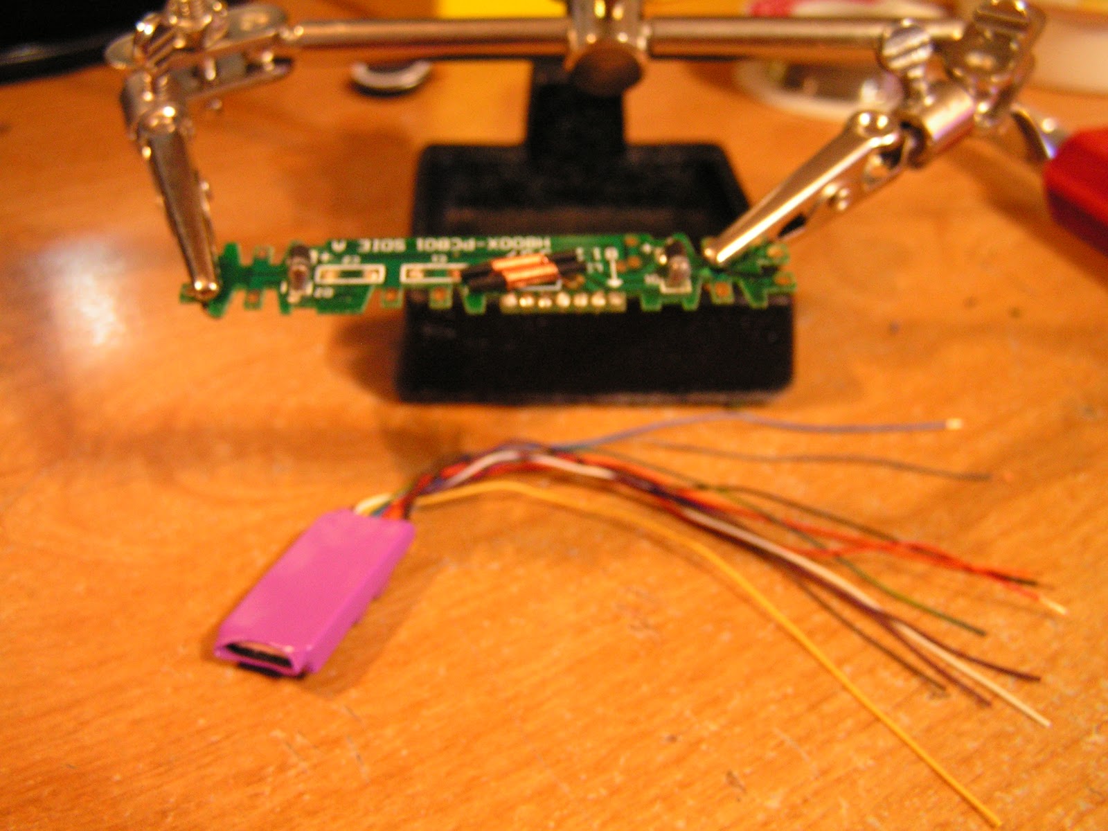
On this install I will include the Bachmann PC Board, with the yellow caps removed. I removed the board from the 44 ton chassis because it is easier to solder this way. Here I have the board mounted and ready with the decoder underneath it.

I stripped and tinned the decoder wires in preparation to solder. I will not be using lights on this loco so I will not need the yellow or blue, and I will use a chuff cam so I do not need the brown wires.

I use a solder pencil with a small sharp tip, thoroughly cleaned and tinned. I simply lay the tinned wire onto the board and touch the iron, it happens that fast. Here I have the red, orange, black and grey wires connected. (motors leads and left/right rail leads)

Tsunami includes a capacitor to add if you wish, it helps power the loco over dirty track. I chose to install it, and according to the instructions, blue wire goes to +, green to - .

The MDC Climax shell, I plan on installing the speaker to the roof.

Here I show the speaker enclosure glued in place.

Here is everything wired up.

Another picture showing the speaker installed.

I put the loco on the programming track, everything checked out fine, and I set the loco address. Then I put in on the layout (pictured here) and tested the sound. All is good.
The next step was bundling everything together and show horning it into the shell, after several attempts I cracked the shell. So I put everything down and decided to to wait for another attempt. Sometimes its good to take a break.
A very late update.
I had decided to remove the Bachmann board and "hard wire" the decoder in place, mainly because the operation was erratic, the unit ran well forward, but terrible in reverse. The loco ran excellent before this upgrade with a standard Digitrax Decoder, so I suspected electrical/electronic issues. When I hardwired the decoder, I had no movement forward or reverse, but the sounds worked perfectly. After some troubleshooting with a multi meter, the decoder was not putting out any voltage to the motor. I went to the Soundtraxx website, downloaded the warranty/repair form, filled it in and mailed it. A new decoder arrived in the mail Wednesday, no charges to my credit card and completely covered under warranty. Thank you Soundtraxx. The pictures below show how I hardwired the loco, using heat shrink tubing (recommended) although I don't recommend using common electrical tape to bundle and tape everything don;t to the chassis, kapton tape is the way to go, which I did once I picked some up.

In the above picture, I have soldered the white wires to the front and rear electrical pickups, the wires are ready to solder to the black and red wires (input) of the decoder.

Here the wires are soldered and heat shrink applied.

Above the gray / orange wires are soldered to the motor wires, and heat shrink applied.
The lighting wires will not be used, and in this instance the cap wasn't installed because I was having issues with programming this decoder, and I wanted to remove the capacitor from the equation.

The bundle taped to the chassis, again kapton tape will be used.

Two purple wires to be soldered to the speaker.

Soldering complete. As I stated earlier, the sounds worked perfectly, but no motor movement. I have the new decoder from Soundtraxx, now I have to make time to do it, please stay tuned.
UPDATE 04/15/2012
I finally got around to installing the new Tsunami TSU-750 Light Logging decoder into my 44 T chassis/ MDC Climax shell. The original decoder was defective and replaced by Soundtraxx under warranty.


First soldered the Orange wire from the decoder to one side of the motor.

The other motor wire (gray) from the decoder was soldered to the motor lead. This was easier than having to disassemble the chassis for clear access to the motor, I preferred to make a butt connection.

I install heat shrink tubing on all connections......

...and used my soldering iron to shrink the tubing over the soldered connection.

Here is the decoder, with all connections soldered. Notice I included the optional capacitor.

The lights will not be used on the loco, so the yellow and white wires were not used. The brown wire is for a chuff cam, again, this feature was not used on this install.


The loco chassis was prepared for the "bundle" to be attached. While I was in there, I went ahead and oiled the gears. I then used kapton tape to carefully attached everything to the chassis. The decoder was fitted on over the rear truck, the capacitor over the front, and the speaker was mounted on the inside roof, directly centered on the chassis. It was a tight, but it fit. The only CV's I had modified was the loco address, I have not modified anything else. The videos below are a tests with the default CV's.
No comments:
Post a Comment